It is no secret that there have been some great advances in the realm of concrete additive manufacturing. However, one of the major drawbacks of this fabrication technique is that the elements must be self-supporting during printing. While most other additive manufacturing materials can overcome this by using a secondary printed support structure, alternative strategies have to be developed for materials such as concrete.
This 4TU project explores the possibilities of combining concrete additive manufacturing with a temporary support surface. By printing on a free-form surface, more intricate geometries can be realized. A number of potential applications have been outlined, however the principle focus is combining concrete additive manufacturing and casting. The end result is a partially-printed pavilion using a completely digital design-to-fabrication workflow.
Although additive manufacturing (AM) is a fabrication technique which has been around for the past 20 years or so, it is only now that we are starting to see its applications emerge into the built environment. Whilst metals, plastics and other composite materials are also being explored for their use in the Built environment, it is concrete that shows great potential for large-scale additive manufacturing. Concrete Printing techniques already allow for the rapid fabrication of large-scale structures with minimal material waste, as already exhibited by Winsun and the fabrication of 1,100 Sqm Apartments in Jiangsu, China.
Concrete that shows great potential for large-scale additive manufacturing.
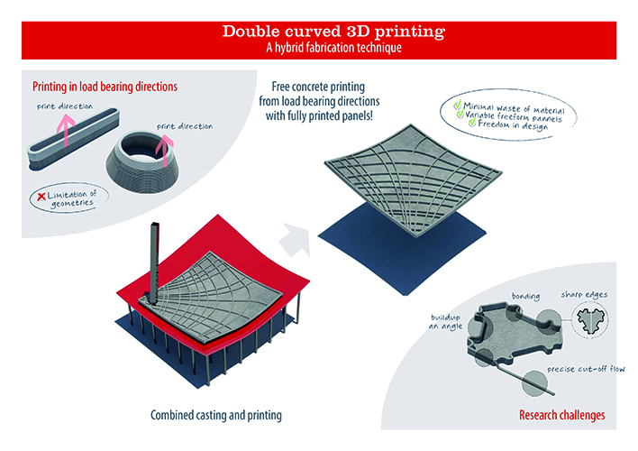
Whilst this does indeed allow for the rapid fabrication of concrete structures, most elements printed remain as 2.5D rather than 3D. This is due to the fact that extruded material must be self-supporting during printing in order to avoid collapse, imposing somewhat of a geometrical restriction. Most other printing materials can overcome this by printing a temporary support structure, however this is not the case with fluid materials such as concrete. Instead, a temporary surface is proposed as a means of support to printed concrete.
The adaptable mould developed at TU Delft served as a means to provide such a surface. Consisting of a silicone surface connected to a bed of adjustable pins, double-curved surfaces can be produced in a similar fashion to milled surfaces. The main difference being that no material waste is generated since new surfaces are defined by adjusting the pin-bed. Prior to the 4TU Project, this system was used for casting free-form concrete panels. The combination 3D concrete printing and an adaptable mould resulted in a hybrid manufacturing technique consisting of two complimentary fabrication techniques.
Three Potential areas of research were identified through this combination. Firstly, the potential for fully-printed concrete panels. For this, It is proposed to use differential growth algorithms to generate print paths over any given surface. The second potential identified was the printing of structural ribs following stress-lines to provide reinforcement to panels. However, the chosen theme was a combination of 3D Printing and casting concrete. In this, complex geometries are defined by printing a boundary into which concrete is cast. The advantage to this approach is that complex, free-form concrete panels can be realized without the need for complicated moulding systems.
Complex geometries are defined by printing a boundary into which concrete is cast.
Design Overview
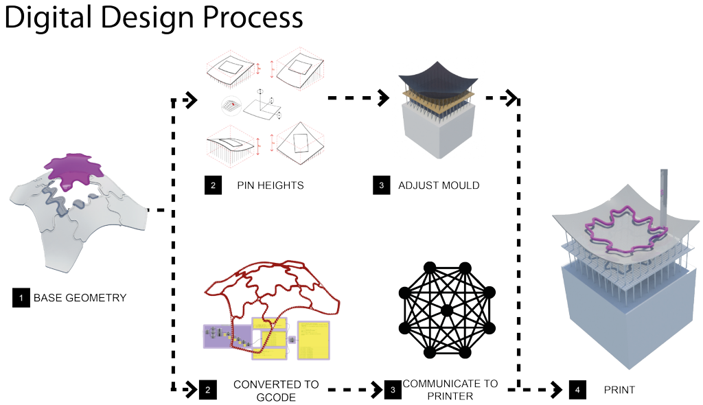
In order to study the proposed manufacturing concept, a shell structure consisting of complex interlocking geometry was designed and printed. The basic principle of realizing the design consists of first creating a digital model of the structure using parametric design tools. Each individual panel is then digitally oriented onto an adaptable mould and G-code is generated by dividing splines that define the perimeter of the object. Once the physical mould is adjusted to match the digital mould, the Gcode is sent to the printer and the geometry is printed. Finally, concrete is cast into the printed shape and left to cure for 24 hours after which it is demoulded.
Fabrication Process
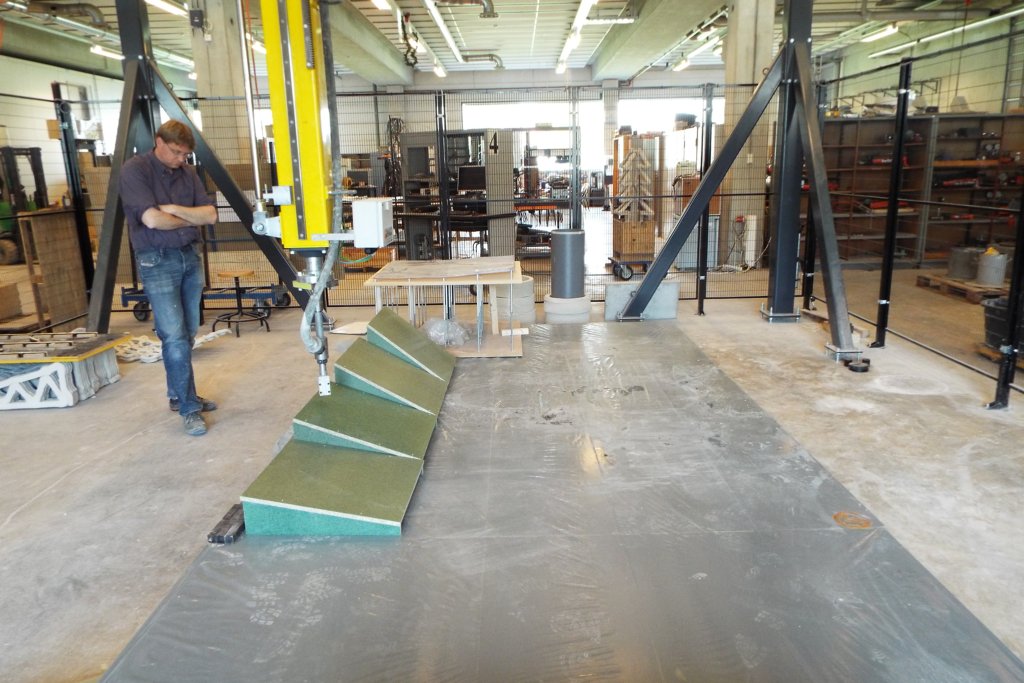
Both the 3D Printer and adaptable mould have their own set of physical limitations. Thus, a number of variables and constraints were set by studying the two technologies. Firstly, the maximum slope angle on which concrete can be printed was found to be 40 Degrees, after which material had a tendency to curl up and distort. This value was used to limit the maximum curvature of the form-found shell structure. Due to the printer’s incapability to print right angles, a minimum turning radius was also determined and was used to generate the tessellations for printed geometry. The end result is a 2.5 m x 2.5 m shell with a maximum slope of 35 degrees and minimum turning radius of 150 mm, consisting of a total of 9 Print-And-Cast panels.

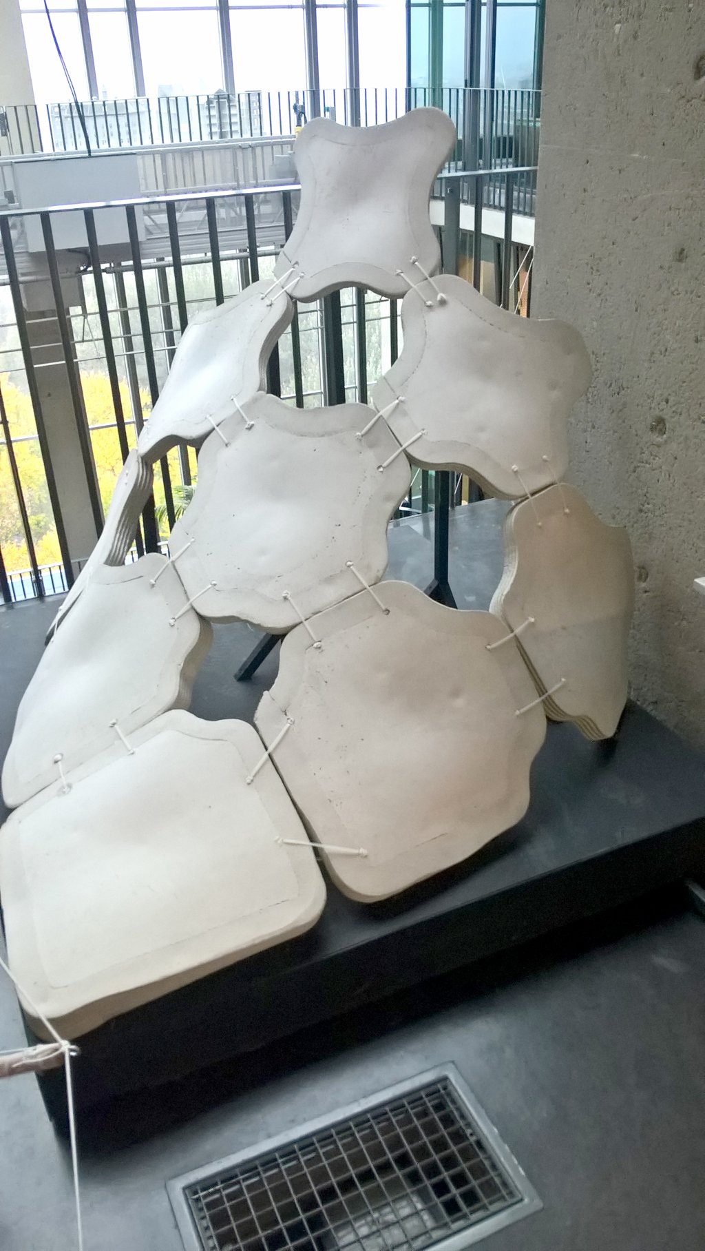
The end result is a 2.5m x 2.5m shell consisting of a total of 9 Print-And-Cast panels.
In order to have a design process which consists of a single file from design to fabrication, a custom g-code generator was created using Grasshopper 3D. This was also necessary because slicing techniques used in traditional additive manufacturing could not be used since a later-wise approach was not used. Instead, the geometry is defined as a spline and is divided into a number of points depending on curvature of the curve. These points are then expressed in terms of their relative co-ordinates and communicated with the Printer. An additional bespoke script was generated to take into account collisions of the Printer Nozzle with the Surface. This was required because printing was not done perpendicular to the surface meaning that the physical nozzle had a tendency to collide with steep surfaces. The way this was corrected was by determining the intersection between the nozzle and surface at every co-ordinate and raising the point such that no intersections occurred. The corrected print path is then defined by interpolating the raised points which is then converted into G-Code.
Final Structure
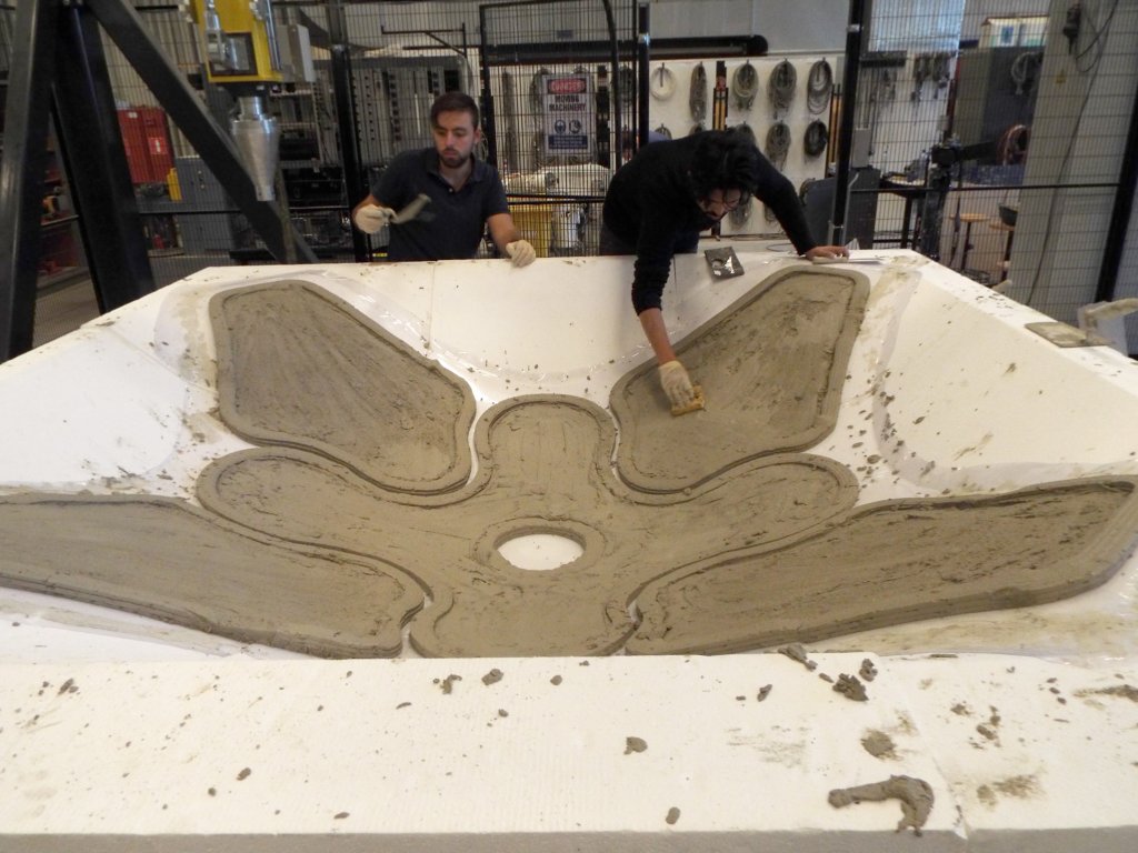
The final structure is printed in a single print pass taking approximately 20 minutes to complete as shown in the image below. After the individual panels are printed, plasticizer is mixed in with printed concrete and cast inside the panels. These are left to cure for 24 hours and demoulded as an inverted shell structure. This is later temporarily propped up and held together through mortar joints.
Challenges and conclusions
The project was limited to a relatively small 2.5 m x 2.5 m shell structure and the geometries printed were kept relatively simple so as to focus on refining the design process. However, given that the physical constraints of the printing process have been established it is easily imaginable that scalability and increase of geometrical complexity can be achieved if boundary conditions are maintained. Moreover, the project focused on combining printing and casting, however other directions such as generating print paths which follow stress-lines could serve as future areas of research using the same basic design process.
Team:
Delft University of Technology
Chris Borg Costanzi, MSc., dr.ir. Roel Schipper
Eindhoven University of Technology
dr. ir. Freek Bos, Zeeshan Ahmed MSc., Rob Wolfs MSc.


